Recent Technical Artist tools I've developed for Maya, Houdini and Photoshop...
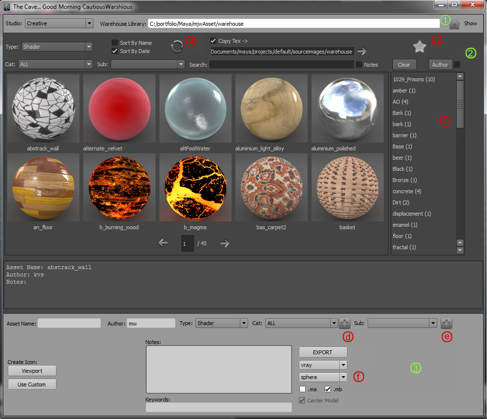
:::Asset Management System (Maya)::: The Asset Management Tool is a utility to import and export models, scenes, shaders, scripts and proxys How To Use
-The icon above the keyword window will Clear all keywords (Clear) from the search textfield. -The asset name, author and notes associated with any asset will be shown in the window directly below the the preview window
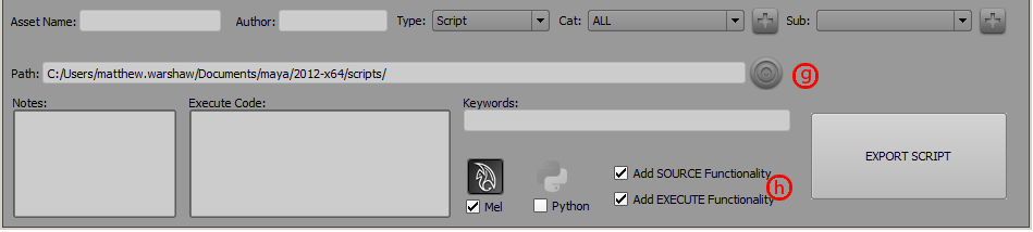
5. Edit Mode (shader/scene/model): The lower UI will change to edit mode if you right click on an asset and choose edit
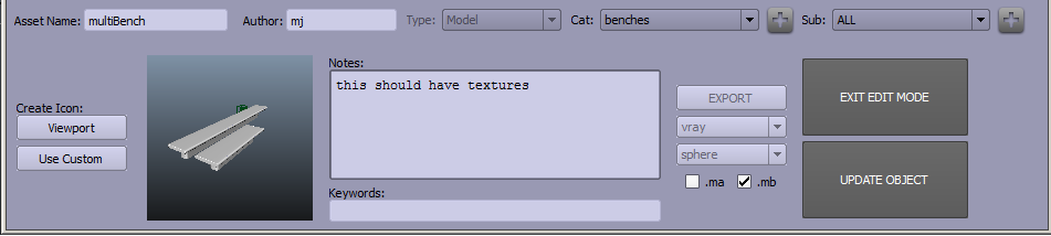
This tool manages Vray Object IDs and resulting multimatte render channels. It keeps track of the most highest Object ID in the scene and allows the user an interface to add selected objects to the next Object ID, a current ID and query various related properties. How To Use
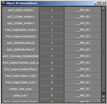
-OBJ IDs: This option menu displays all Object IDs by number and the opposite "Contained Objects" option menu displays the objects that have that Object ID. (i.e the above example shows that an object 'frontengine1|window_side_nuts' has a Vray Object ID with value 8 -Add to NEW OBJID Set: Any selected object will be added to the Object ID group with the value one higher than the highest object ID in the scene (i.e in the above example, if 8 was the highest object ID, any selected object would be assigned Object ID 9). If an ID set has been deleted for some reason, the new ID will be assigned the number of the deleted OBJID. When the tool is run for the first time on a scene, it will query the scene for all vrayproperties nodes and and will start IDing objects from the number after the highest value The new Object ID value would be added to the next available multimatte channel. A new multimatte channel will be created if there are no available channels in the current multimattes. -Add to CURRENT OBJID Set: Any selected object will be added to the Object ID group with the value shown in the above 'OBJIDs' option menu. (i.e in the above example any selected object would be assigned Object ID 8) -Clear All Object IDs: All Vray object IDs will be removed from the scene. The tool will start IDing objects from the number 1 again. -Multimatte Channels: This option menu displays all Multimatte Channels by number and the opposite "R" , "G" and "B" texts display the object IDs that are attached to the R, G and B channels of that multimatte. Whichever multimatte channel is selected in this drop-down menu will colour the corresponding objects Red, Green and Blue based on their object IDs. I.e in the above example, because __M_001 is selected in the option menu, the Object IDs 1 (R), 7(G) and 8(B) are the attached object IDs. Therefore all objects with object ID 1 are shown in red (window, front window), objects with object ID 7 are shown in green and objects with object ID 8 are shown in light blue -Clear All Multimatte Channels: All Multimatte Channels will be removed from the scene. The next multimatte pass created will be named __M_001 -Query Object: Whatever object is selected (only the first in a multi-selection) will have its Object ID and multimatted channel displayed in the textfields immediately below.
-Show Spreadsheet: This will display a spreadsheet of all objects assigned object IDs, which object they are assigned to, and which multimatte it is assigned to. Everything in the spreadsheet is selectable by clicking in the appropriate field.
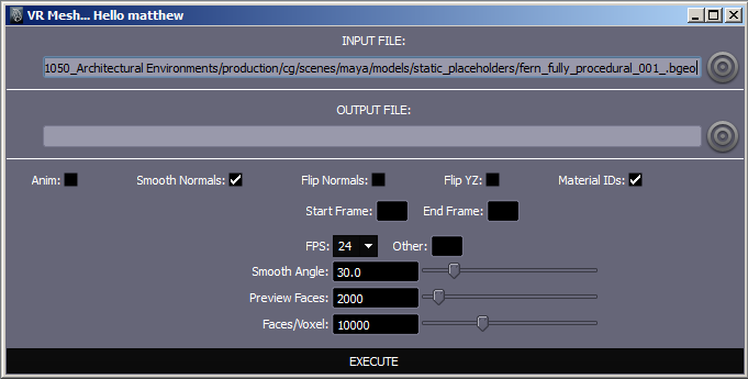
This tool allows the user to input a .bgeo, .geo, .obj or .ply file and outputs a vrmesh. It can be used in animate mode to output an animated vrmesh.
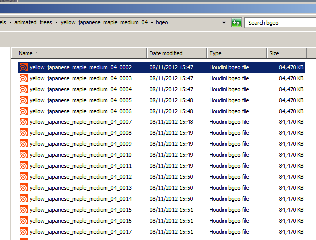
How To Use -Input File: Select any of .bgeo, .geo, .ply or .obj file formats for the input. If you want to output an animated vrmesh, you must have all geometry files in a single folder, with each file named '...filename...frameNo" (i.e:
Select any file in the list and check the checkbox labelled "anim" and the tool will create an animated vrmesh. -Output File: You may specify a folder and filename for the outputted vrmesh. If not set, the output will default to inputPath.vrmesh
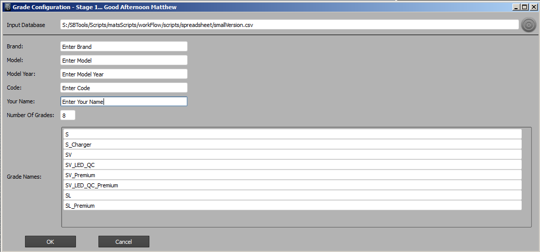
This tool is the first stage of a 2-stage car-prepping tool-kit. How To Use
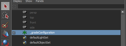
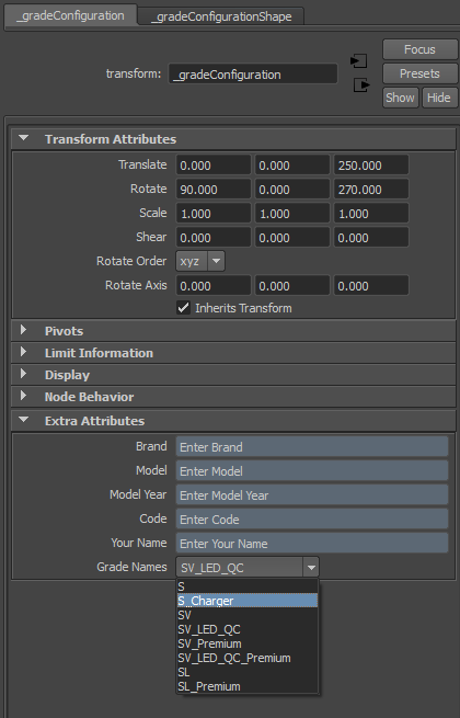
The user has the option to enter a .csv file as the template for configuration. This file should have been created from a .xls file by selecting the relevant fields and clicking save as .csv. If a .csv has been referenced, the Grade Names field should be automatically populated. If not, or if no .csv has been specified, the user must manually enter the number of grades and type their names into the relevant text fields. The user should also fill out the Brand, Model, Model Year, Code, and Your Name fields. On clicking OK you should see confirmation that a locator named _gradeConfiguration has been created, which should show up in your maya scene: (it will hold attributes pertaining to the entered fields and should not be deleted)
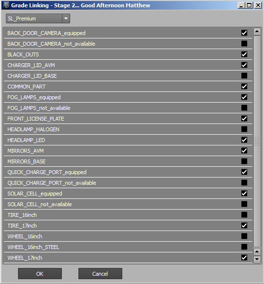
:::Car Grade-Display Linker (maya)::: This tool is the second stage of a 2-stage car-prepping tool-kit. For this tool to function, there must be a locator in the scene called _gradeConfiguration (created by the Configuration stage of the 2-step process above): How To Use
The user should not rely on this being correct (especially in the early days of the tool) and manually check that the spreadsheet data has been correctly parsed. One thing I noticed in testing is that a display layer may have slightly different naming to the display data in the spreadsheet (WHEEL_17inch vs WHEEL_17 for example) which will obviously throw the tool. This could be solved by changing the display name in the .csv file or in the scene to match up. If no spreadsheet had been selected in the Configuration stage, the user must manually enter which display layers should link to which grades by checking appropriate check boxes in the UI above. Once all data across all grades is correct click OK to finalise this tool-kit. You will end up with attributes on the _gradeConfigurator node that display the Brand/Model e.t.c as well as the attribute Grade Names which should allow you to select the current grade and have display layers update automatically.
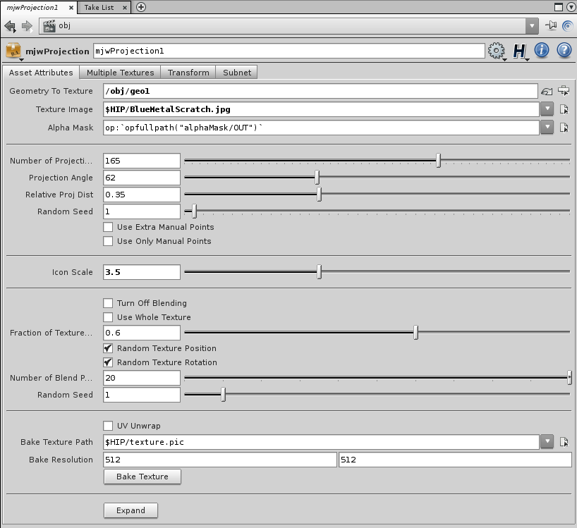
:::Projection Shader (houdini)::: This digital asset enables the user to project a single texture, or multiple textures onto any piece of geometry and bake out a texture of this projection. How To Install: The mjwPROJasset.otl containing the asset must be added to the env path, so it can be used either if you edit your houdini.env file or if you install the digital asset manually in houdini using file/install digital asset library: The digital asset is at the scene level, so in an obj context simply: tab/mjwProjection to lay down the asset. How To Use
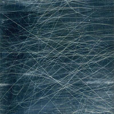
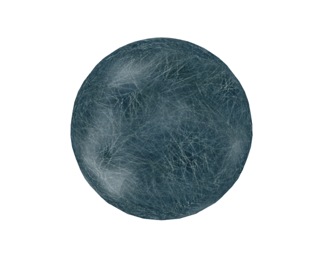
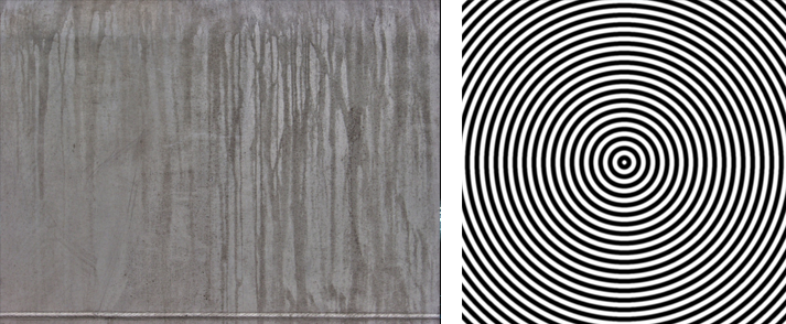
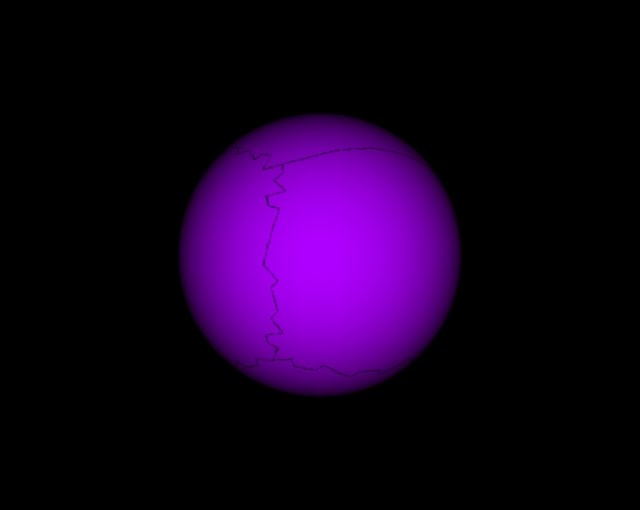
First, the tool needs an object to texture. The object should be a polygon (not sure if it works with nurbs) and it is advisable to have some UVs attached. They don't need to be good UVs and the tool has the option UV unwrap to add UVs itself but this may make things awkward. Link the tool to the object in the Geometry To Texture field. The object (sphere in this case) MUST HAVE ITS DISPLAY FLAG OFF -The Texture Image field points to the image that will be the primary texture projected onto the object. In this example it points to a square texture named BlueMetalScratch displayed below:
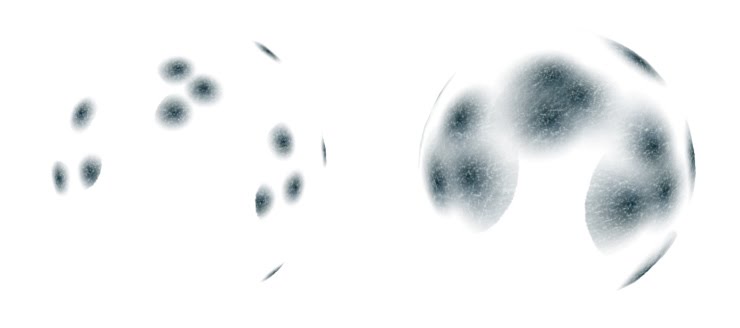
-The Alpha Mask field points to the image that will determine the falloff of each projection. It will have no effect if the Turn Off Blending checkbox is enabled. By default it points to a copnet within the asset named alphaMask which is a radial falloff from white to black. Dive into the subnet to view it in in composite mode. Alpha Mask can obviously be redirected to point to any image file, it will use the r channel to determine the alpha blend. -Number Of Projections is self evident. -Projection Angle is the allowed angle between each projector and point being shaded. You can think of it as the lighting angle. Below is an example of a smaller and larger Projection Angle:
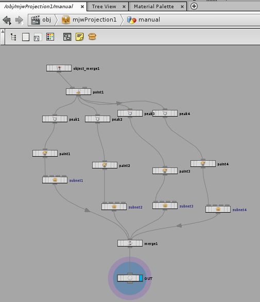
-Relative Projection Distance is a measure of the distance between the object and the projections. It is related to the Projection Angle in that a larger Projection Angle is equivalent to a larger Relative Projection Distance. If the geometry object has dramatically varying contours, it may be a good idea to set the Relative Projection Distance further away from the object. The next 2 parameters relate to adding manual projections. This may be needed if the random positioning of projections has left some areas of the object "unprojected". To add manual projections, dive into the mjwProjection asset and into the manual geo node. You must select allow editing of contents from the asset menu to add manual points.
Any points that plug into the OUT node will have projectors instanced to them. I have set up some paint nodes attached to peaks around the object so that you can just paint some points where you want them. It is a good idea to disconnect paint from the subnet it is connected to before painting and reconnecting afterwards. The subnet has a parameter called numPoints that will determine the number of points scattered over the area you just painted. Any other method of creating points is fine The projectors should be correctly oriented. There is a manualTemplate node included in the subnet in case you want one with default settings. It should be renamed to manual if you want to use it. -The Use Extra Manual Points then adds these projectors to the randomly positioned ones. -The Use Only Manual Points uses only these points and none of the randomly positioned ones. -Random Seed is the seed used for the random positioning of the projectors. -Icon Scale is the scale of the icons representing the projectors. It is very useful to have this set to a reasonable size so that you can see where you are projecting. The next section sets parameters related to the texture mapping. Turn Off Blending disables all blending and falloff. This can be useful for error checking or just getting quicker renders in initial stages Use Whole Texture tells the tool to use the entire texture as the projection map. If turned off, you can specify the size of each texture projection using the Fraction of Texture parameter. In the above example, each "projector" would project the highlighted section on the left if Use Whole Texture was ticked and the highlighted section on the right if Use Whole Texture is off and Fraction of Texture is set to 0.5:
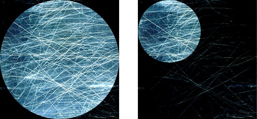
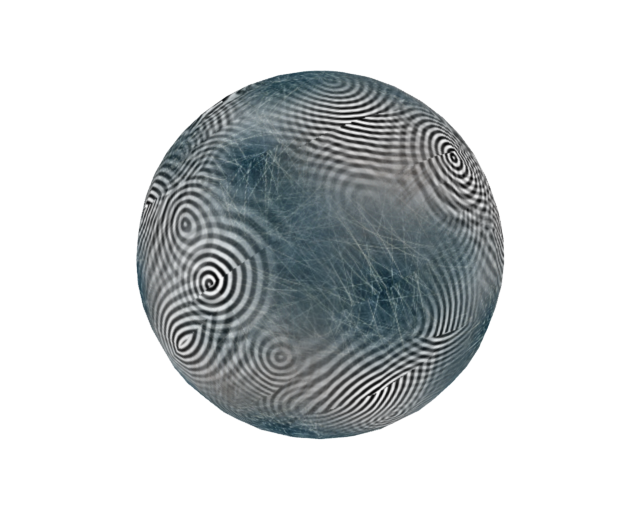
If Use Whole Texture is off, then the parameter Random Texture Position will randomly select a place on the texture to sample from. -Random Texture Rotation will rotate each projection by a random amount. -Number of Blend Points determines how many projections will be used in the blending process. If it was set to 2 for example, the closest 2 projections will be used for all blending. These value shouldn't need to be set above 30 or so. -Random Seed is the seed used for the random positioning and rotation of the texture selection. UV Unwrap will apply default UVs to the object being shaded within the mjwProjection asset to allow a texture to be baked out, it will not affect the geometry object that the mjwProjection asset is linked to so that geometry will have to have a UV Unwrap applied to it to get reasonable results. This method is not ideal. -Bake Texture Path and Bake Resolution are self evident. -Click Bake Texture to bake out a texture to Bake Texture Path. It will run a command line function which means it will seem like everything has finished after a couple seconds but it will slowly be baking out. I'm getting bake times of roughly: 512 x 512: 30s - 2min 1024 x 1024: 5min - 10 min After the texture is baked out it can be used however you like. It should have alpha information that represents the strength of the projections from different points. There is a shader in the shopnet called "Decal" that is set up to use the texture referenced in Bake Texture Path. The mjwProjection subnet must have it's display flag switched off to get sensible renders once the baked texture is applied (or at least the Instance Points node should be turned have it's display flag switched off. I'm getting the following render from the above settings:
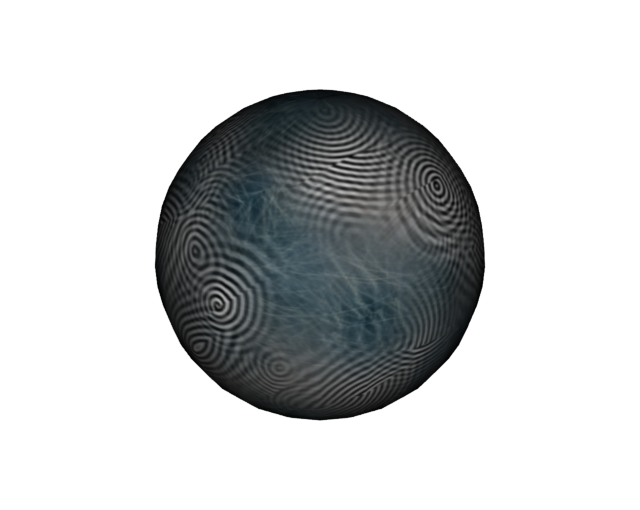
And the following render from reapplying the (512 x 512) texture baked out by the above settings:
The Multiple Textures section allows the user to project multiple textures and blend between them randomly. All the above settings will still apply: 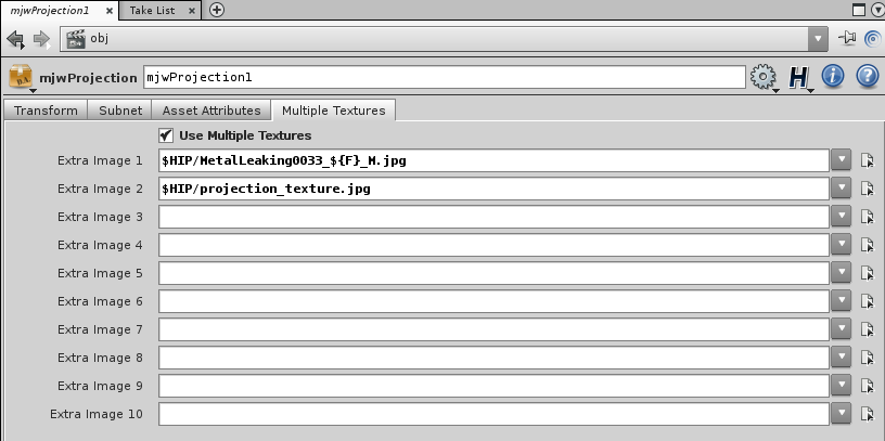
The above textures look like this:
I'm getting the following render from the above settings:
And I get a render like this when reapplying the baked texture:
Re Apply Texture: The baked texture can be re-applied by connecting the original geo (obj/sphere in the example) to the mjwProjection/shopnet/bakeTexture. the mjwProjection asset must be turned off when you do this. Possible Black Line Error: Often the baked texture will not quite fill the UV space, this can result in one pixel black lines around the uv joins when the texture is re-applied:
If you get a result like this, it can be solved by expanding the texture. This process is all automated within the asset. You can view the expanded result by switching the shader to mjwProjection/shopnet/expandTexture. You can update the texture by pressing the Expand button after the texture has been baked. This Button can be hit multiple times and the texture will be rewritten each time
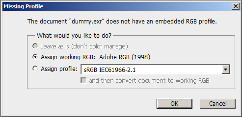
:::Stacking Script (Photoshop)::: This tool allows the user to stack a combination of ID and non-ID files. It extends Photoshop's stacking script enabling the stacked files to be brought in to the correct colour space. It can also create alpha groups for the inputted ID layers. -----------------------------------------------------------------------------------------------------How To Use The script will open a dummy .exr file and ask for an embedded RGB profile. It must do this to avoid complications in trying to script this process. You MUST select "Assign working RGB: Adobe RGB (1998)" or the script will not stack in the correct colour spaces
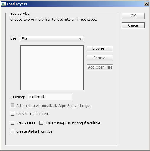
After you click OK you will be presented with the main UI:
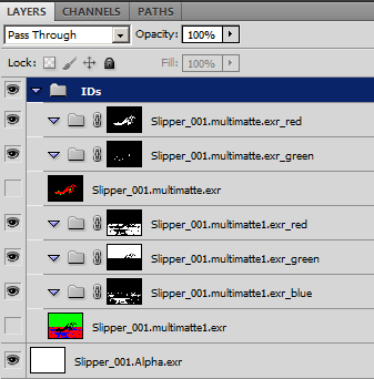
-Browse to select all files that will be stacked. -ID string is used to separate ID layers from non-ID layers. It is crucial that you set this to a string that appears in ID files but not in non-ID files (an example might be 'multimatte' if the IDs were created by using vray multimatte channels or might otherwise be something like '.ID.') -Convert To Eight Bit it will convert the final document to 8-bit -Vray Passes and Use Existing GI/Lighting if available will attempt to construct a series of Vray Passes based on a sensible Vray lighting worflow (these options may be scrapped if they are not deemed useful) -Create Alpha from IDs will create a series of nested groups for each colour channel (as below)
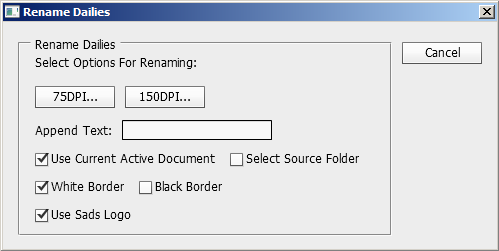
:::Rename Dailies (Photoshop)::: This tool allows the user to save out 75dpi/150dpi jpegs of the current PSD file or multiple PSDs, with the company logo and current file name added in black or white How To Use Execute using file/scripts/Rename_Dailies_ASSET from within photoshop You should see the following UI:
-Any text you add to the Append Text textfield above, will be added to the file name text that appears at the bottom of the image. For example if we wrote "extraText" in there, and the filename was "dummy.psd", we would see "dummy_extraText" at the bottom of the image. -We can tell the script to process the current active photoshop document (in which case the resulting dailies jpeg will be left open in case the user wants to change the text) or we can select a folder and the script will process every file in that folder (all files will be closed after they are processed) -Choose whether you want the script to place a white border with black text, or vice versa -Hit either the 75DPI button or the 150DPI button to begin. Enjoy |
||||||||